


Mixer: line input board
 2 -
2 - 
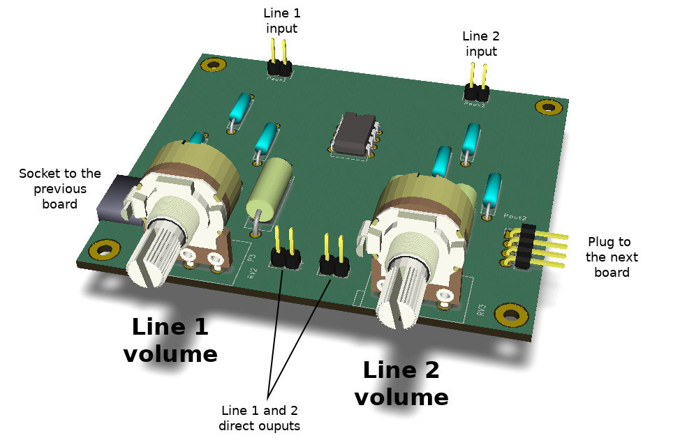 Figura 1: The line input board for the modular mixer.
This board allows to input into the mixer signals with line audio levels, that is, coming from consumer devices like computers, mp3 readers or mobile phones. To implement a line input only one opamp is required; anyway on a single LM358 there are two opamps. Therefore this board implements two line inputs, and it is twice wide with respect to the other boards.
1 - Circuit characteristics
The circuit has the following elements:
- Two potentiometers to regulate the two audio channel volumes, placed on the user panel.
- Two audio inputs on the back of the circuit.
- Socket to the previous board and plug to the following board to share all the common signals (Vcc supply voltage, ground, audio signal and Vcc/2 bias voltage).
- Direct outputs 1 and 2 to connect directly an external device (a recorder, an amplifier, etc). The signal is decoupled from the audio inputs, and its volume is regulated by the potentiometers. Since these outputs are connected directly to the opamp output, the connected device should have a high impedance input; headphones, which typically have low impedance input, are not recommended.
It should also be noted that the volume regulation is quite linear, as shown in Figura 3.
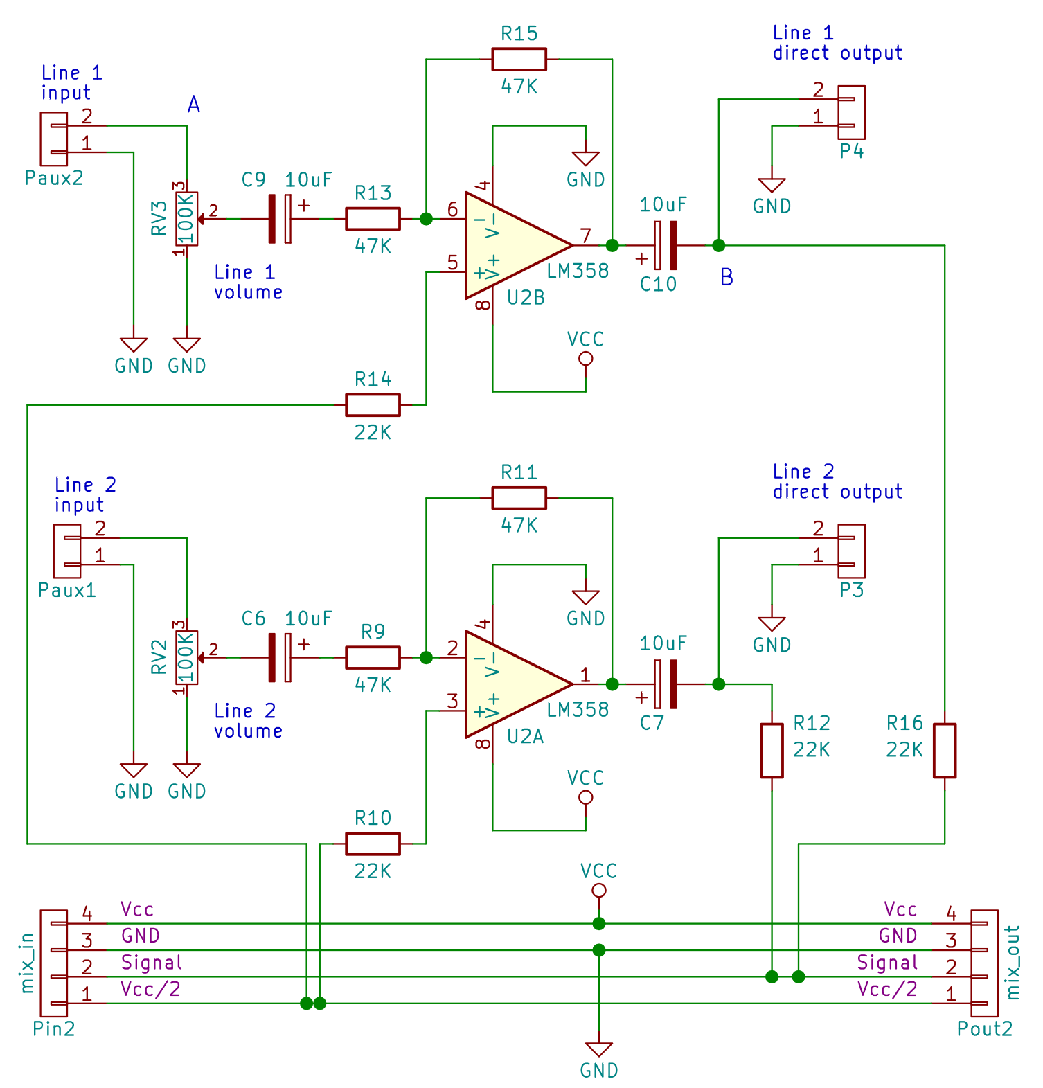 Figura 2: The schematic for the mixer line input board.
2 - Assembly notes
The circuit is not difficult to build, and it has a 8cm x 7cm size, that is the double of the basic mixer board. Pay attention to the the L pins for the socket and the plug connectors to the other modules. Indeed, to maintain a constant distance among the potentiometers on the user panel the mixer boards should match perfectly.
3 - The design
The line input board is made of two identical circuits; only the upper one in the schematic with the U2B circuit will be considered. The opamp is used in its inverting configuration, a very common and well documented application. When the RV3 potentiometer shaft is turned towards the Paux2 input line, that is when the volume is maximum, it doesn't affect the signal at all. In this case the input signal at Paux2 pin is connected directly to the inverting amplifier input, and the output voltage on the P4 connector is:
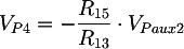
The purpose of this circuit is to decouple the input signal from the rest of the mixer. Therefore we choose to have a gain of 1, that is, we choose R15 = R13 = 47 KΩ
On the other side, when the potentiometer shaft is turned towards ground, the amplifier input voltage is zero, and therefore the output voltage is zero.
When the potentiometer shaft is at an intermediate position, the voltage is:
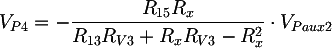 where Rx represents the potentiometer shaft position, and it is a value between 0 and RV3. The potentiometer dynamic is quite linear and it is shown in Figura 3.
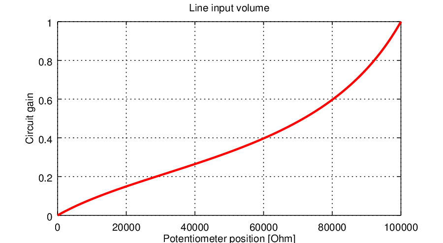 Figura 3: The line input volume as a function of the potentiometer position.
Finally, the R12 and R16 resistors are part of the summing circuit in the main module, as explained in its page. The C9 and C10 capacitor prevent the bias continuous current to flow into external devices.
3.1 - Minimizing bias currents
As said in the main module article, to reduce the opamp bias current effects the equivalent resistances as seen from V+ and V- should be equal. The equivalent resistance as seen from V- pin is not constant, due to the potentiometer. Anyway, considering the the case when the potentiometer is at its maximum or minimum, it is R15 // R13. Therefore:

3.2 - The input resistance
The input resistance as seen from an external circuit isn't constant, and it varies between RV3 (when the volume is at its minimum, that is, when the potentiometer shaft is connected to ground) and R13 (when the volume is maximum, that is, when the potentiometer shaft is shortcircuited towards Paux2 input).
Bibliography and other documents
Copyright 2014-2026 electroimc.com