


Mixer: mic input board
-
 3 - Mixer: line input board
- Indice
- 4 - Mixer: mic input board
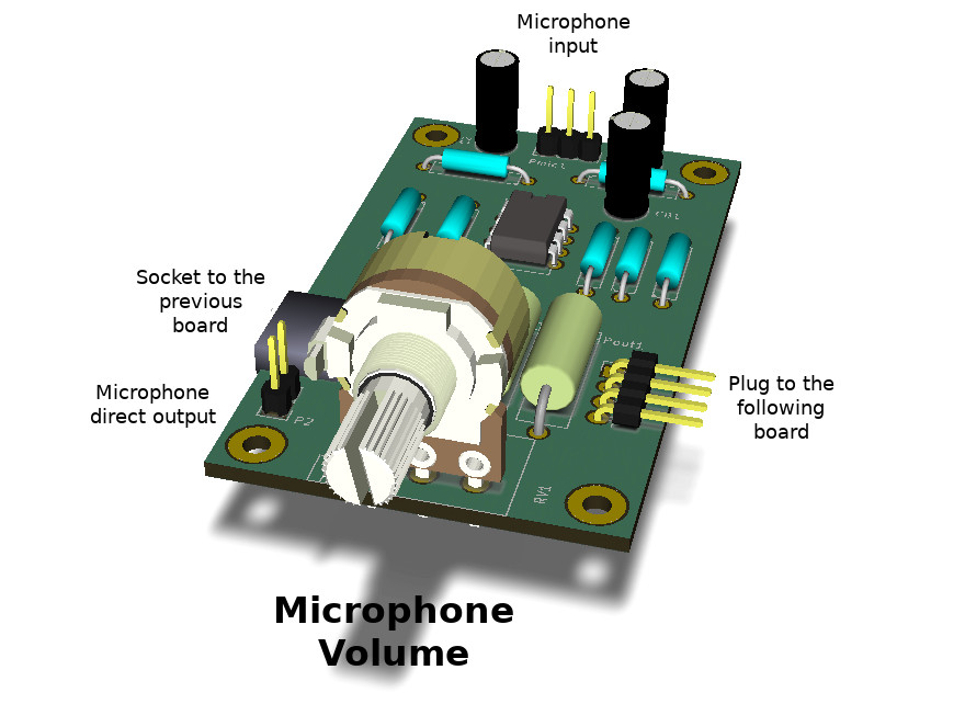 Figura 1: The photo of the microphone board for the modular audio mixer.
The mic board is a simple microphone preamplifier which adapts the signals coming from a microphone to the line audio levels. It has two functions:
- Convert the signal from a balanced type (hot signal, cold signal, ground) to an unbalanced type (signal and ground).
- Amplify the weak signal from the microphone (typically, a few millivolts);
To perform these two operations the board uses two operational amplifiers, and therefore a whole LM358 microchip.
1 - Circuit characteristics
The board presents a few similarities with the line input board:
- Microphone input: it is designed for balanced signals, composed by hot wire, cold wire and ground. This kind of signal is typically found in professional microphones, that is the ones that have the XLR connector, also called Cannon in a few countries. In case of an unbalanced microphone (two cables only, signal and ground), for example with the jack connector, the pin 3, the cold one, has to be shortcircuited to ground. The two types of connectors are shown in Figura 2.
- Direct output: this output can be directly connected to an external device (a recorder, an amplifier, etc). The signal is decoupled from the microphone, amplified and regulated by the volume potentiometer. The device connected to this output should have a high input impedance, due to limited LM358 output source; connecting headphones, which typically have low impedance input, is not recommended.
- Socket to the previous board and plug to the following board: socket and plug to share with all the other boards the common mixer signals (Vcc supply voltage, ground, audio signal and Vcc/2 bias voltage).
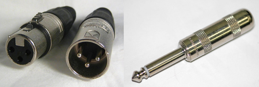 Figura 2: On the left two male and female XLR (Cannon) connectors, commonly used for balanced signals, are shown. On the right a jack connector, used to bring unbalanced signals, is shown.
2 - Assembly notes
The circuit isn't difficult to build, and the board has a 4cm x 7cm size, that are the dimensions of a standard mixer board. As in case of the line input board, pay attention to the pins connecting the board to the other ones, in order to make all the boards match and have always the same distance among potentiometers on the user panel.
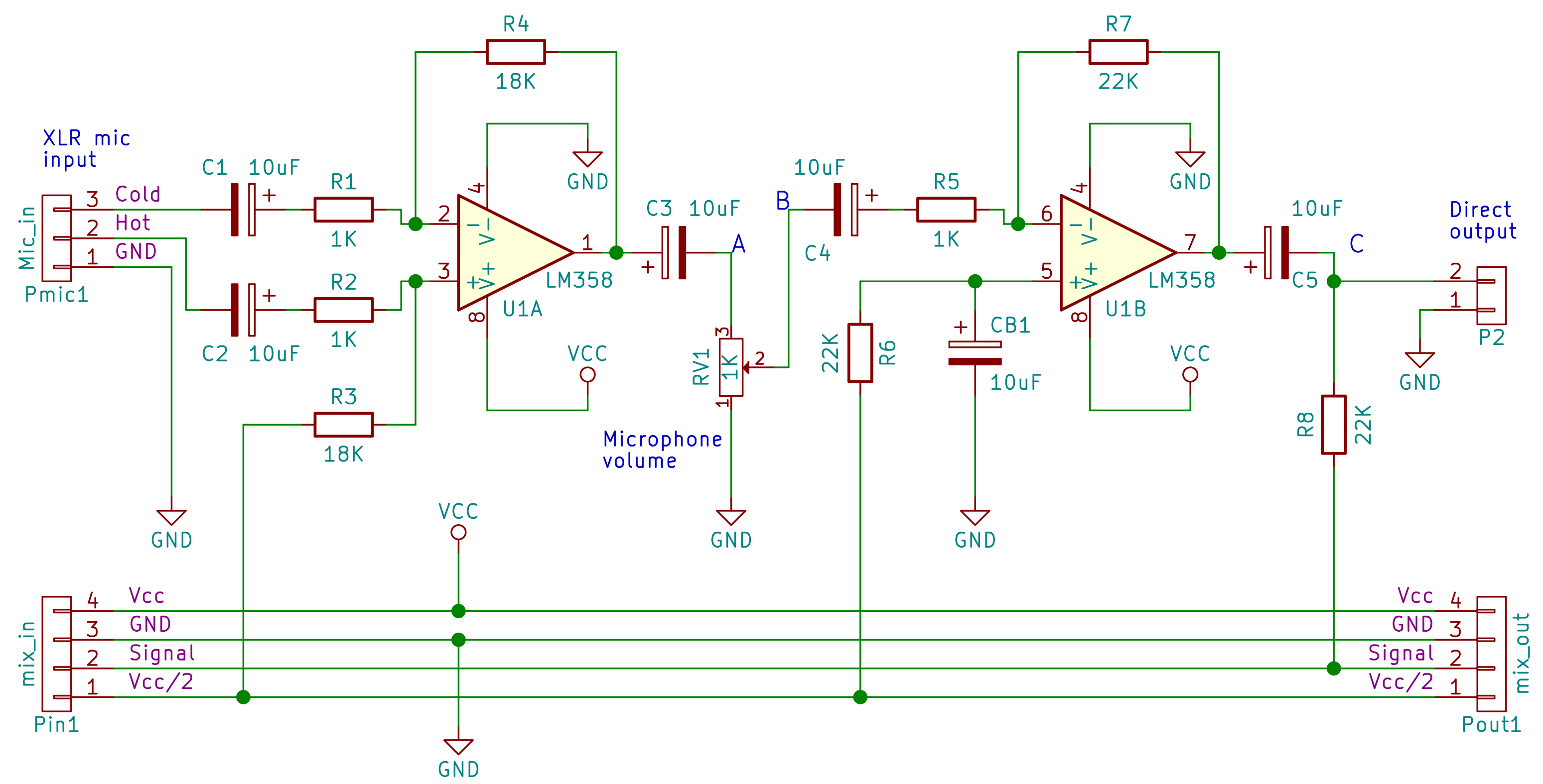 Figura 3: The schematic for the microphone preamplifier board for the modular mixer.
3 - The microphone signals
Before explaining the circuit it is necessary to discuss the characteristics of the microphone signals, because the design of the preamplifier relies on them. Specifically, a few considerations can be made about the balanced line and the low voltage levels.
3.1 - The mic signal levels
Microphone voltage range is usually between 1mV and 10mV, according to the microphone type. An amplification is therefore required to get to the 1V line levels. Assuming a very low voltage, for example 2mV, a gain of α=400 is required to get 1.2V. In this article this value α=400 will be assumed. Its exact value is not important: the potentiometer allows for volume regulation and the adaption to the various mic levels.
A gain of 400 for an amplifier with as single opamp is too high. It's better to split the gain into two stages, each with a gain of 20.
3.2 - The balanced line
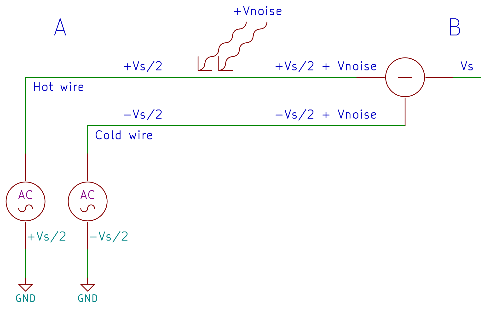 Figura 4: The schematic shows a balanced line and how this solution can theoretically avoid noise.
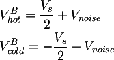
The purpose of a balanced line is to eliminate the electromagnetic noise received by a long wire bringing a Vs signal from a point A to a point B. Instead of using only one conductor with the Vs signal, two conductors are used, each of them bringing half of Vs (hot wire) and the negative half of Vs (cold wire):

Since the two conductors are next to each others in the cable, when an electromagnetic noise Vnoise hits the cable, it sums to both the signals:
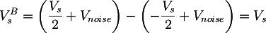
If at the end of the cable the two signals are subtracted, the noise is deleted, and the result is a pure Vs:
The circuit to connect to a microphone balanced line is a differential amplifier, in order to perform the difference between the hot and cold signals.
4 - The design
The circuit is divided in two stages. The first stage is a differential amplifier which converts the balanced signal coming from the microphone into an unbalanced signal, amplifying by 20. The second stage decouples the volume potentiometer from the following boards, and amplifies it by 20.
4.1 - The first stage: the differential amplifier
The first stage of the microphone preamplifier is a differential amplifier, with well known equations; choosing R1=R2 and R3=R4 we can write:
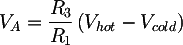 where Vhot and Vcold are respectively the voltages on the pins 2 and 3 of the connector Pmic1. As said before, this stage should have a gain of 20, and therefore we choose R3=R4=20KΩ and R1=R2=1KΩ.
4.2 - The second stage: the inverting amplifier
The second stage is a simple inverting amplifier, which is well known in literature, too, with the following equation:
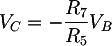 where VC is the second opamp output voltage, for example on the P2 connector, while VB is the first opamp output voltage. Like the first stage, we choose a gain of 20, and therefore we choose R7=22KΩ and R5=1KΩ.
4.3 - The volume potentiometer and the total gain
When the potentiometer shaft is turned towards the pin 3, the first stage output signal is the input of the second stage, and the volume is maximum; in other words, the potentiometer has no effect. On the other side, when the potentiometer shaft is on pin 1, the second stage input is shortcircuited towards ground, and therefore there is no signal at the output. The gain of the second stage when the shaft is at an intermediate position was already presented for the line input board, and in this case is:
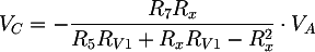
The total gain is therefore the product of the gain of the two stages:
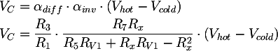 where αdiff is the gain for the first differential stage and αinv is the gain for the second inverting stage. In the Figura 5 the volume dynamic is shown.
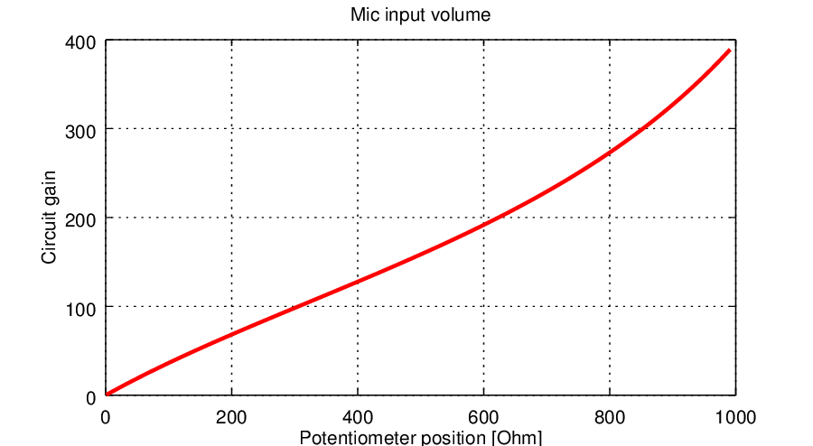 Figura 5: The figure shows the whole circuit gain (the volume) as a function of the potentiometer position.
4.4 - The decoupling capacitors
The C1, C2 and C5 capacitors prevent the continuous bias voltage to flow into the external connected devices. The C3 and C4 capacitors avoid that the continuous voltage gets to the potentiometer. If this would happen, indeed, the potentiometer would overheat when it has too low resistance values; moreover, the second stage would amplify also the continuous voltage coming from the first stage, saturating.
4.5 - The CB1 capacitor
The Vcc/2 signal is a continuous current, with the only purpose of biasing the mixer boards. Anyway in reality it might contain small Vdist noise signals, for example due to the residual power supply ripple. This might be a problem in the second preamplifier stage.
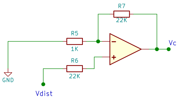 Figura 6: The image shows how the second stage of the microphone preamplifier can be interpreted when the volume potentiometer is set to zero, that is, when the stage input is connected to ground.
When the microphone volume is zero, that is, when the potentiometer shaft is connected to zero, the second stage can be interpreted, from the point of view of a noise signal in Vcc/2, as a non inverting amplifier, as shown in Figura 6. Its gain is:
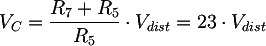
A gain of 23 is enough to amplify the noise until it is audible. Said in other words, to a low volume corresponds a high noise due to a non clean Vcc/2.
To solve this problem CB1 is required: from the point of view of Vcc/2 it is an open circuit, and therefore it doesn't have any influence. From the point of view of Vdist it is a short circuit to the ground, ensuring that the non inverting input voltage is null, avoiding therefore noise at the microphone output when the volume is low.
Bibliography and other documents
-
3 - Mixer: line input board
- Indice
- 4 - Mixer: mic input board
Copyright 2014-2026 electroimc.com