


Cheap measurement of an audio amplifier input impedance
The input impedance of an audio amplifier is a parameter hard to find, and only a few manufacturers offer it. In this article a quick method for evaluating this value with a good approximation is presented; only low cost instruments, which can be usually found in every electronic enthusiast's lab, will be used.
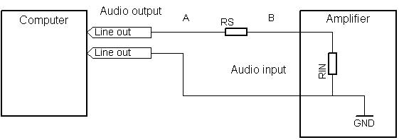 Figura 1: Connection schematic for the measurement of the audio amplifier input impedance.
1 - Required equipment
In the following paragraphs the required equipment will be listed. For every element some theoretical an practical considerations will be done.
1.1. - A multimeter
It's an instrument owned by every electronic hobbyist. The function we are interested in is the alternate voltage measurements. Even the most cheap models have this capability, and usually, though they are designed to work with 50Hz or 60 Hz network frequencies, they can measure correctly also slightly higher frequencies. The multimeter used to write this article is the cheap DT9208A, bought at an electronic fair in the northern Italy in 2010, which allows to measure alternate voltages up to 200Hz.
1.2 - A computer
In absence of a functions generator, we will use the audio card of a common personal computer to obtain a test sine. The sine frequency must be high enough to bypass the capacitors usually present at the audio card output and at the amplifier input. Keeping in account the multimeter limits, a 150Hz is reasonable.
Many ways exist for generating this signal. Using a wav audio file is one option; on the contrary, the mp3 file has to be avoided, since it is a lossy format, and therefore the resulting signal might not be a perfect sine. Programs which turn the pc into an electronic measurement workbench are another solution. A good example is Visual Analyzer.
Voltages at the audio output of a Pc audio card can go up to 1V or 1.5V. These levels are the same ones commonly accepted by an audio amplifier input, and therefore they are suitable for the measurement. The audio card output impedance is usually between 1 Ω and 150 Ω, and since it will be in series with a resistance of many KΩ, it can be easily neglected. Anyway, the proposed method is independent form the source impedance.
1.3 - 10 KΩ and 100 KΩ resistors
We will use these resistors to measure the current absorbed by the amplifier input. Indeed, if the all the multimeters can usually measure alternate voltages, the capability of measuring alternate currents is not so common. Moreover, since the line voltage is maximum 1.5V and the input impedance usually many KΩ, the currents are very low, about some µA.
1.4 - An audio amplifier
It is the object we want to calculate the input impedance of. We should note that this parameter is not constant in frequency: especially in case of single supply amplifiers, decoupling capacitors are present at the input with high pass filtering purposes, blocking all the frequencies below 50Hz. Moreover, the parasitics parameters and the stability protections limit the maximum frequency. A 150Hz measure is anyway enough for an approximative estimation of the impedance, even if it is usually done at 1 KHz.
2 - The measurement method
- Measure the resistor RS to know its precise value.
- Connect all the components as shown in the schematic.
- Turn on the amplifier, after possibly connecting a loudspeaker to hear and be sure that everything is working.
- Turn on the computer and, through the chosen software, output a 150Hz sine at maximum volume. The VA voltage at the computer output is not required for the measurement, but check anyway that it is more than 1V.
- Measure the VAB voltage on the RS resistor.
- Measure the VB voltage at the amplifier input.
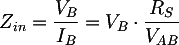
- Calculate the amplifier input impedance as:
- Repeat with another resistance to have a comparison.
3 - A measurement example
As an example, with this method the input impedance of Fenice 20 was measured. It is a T class, 15W + 15W power audio amplifier based on Tripath TA2024C chip. Here there are the results for two values of RS:
| Frequency | VA | RS | VAB | VB | Computed IA | Computed RIN |
|---|---|---|---|---|---|---|
| 150 Hz | 1,48 V | 10,00 KΩ | 0,5 V | 0,94 V | 50 uA | 18,8 KΩ |
| 150 Hz | 1,48 V | 101,2 KΩ | 1,25 V | 0,19 V | 12,35 uA | 15,35 KΩ |
As it can be noted, the obtained impedance is varying, but we can anyway estimate it around 15 - 20 KΩ (really different, for example, from the high impedance inputs based on FET transistors used in some operational amplifier, which are about some MegaOhms).
Bibliography and other documents
Copyright 2014-2026 electroimc.com