


Measure of the maximum power of a supply transformer
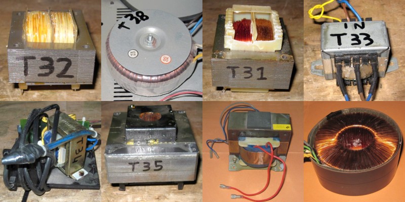 Figura 1: Some transformers for electronic devices with different dimensions, outputs and shapes.
Transformers are common components found in many electronic devices. Up a few years ago they were the heart of the power supply of almost every low voltage device, while in the last years they've been replaced by the switching power supplies, which, for the same provided power, are lighter and more compact. While the measurement of a transformer output voltage is a simple task, an estimation of its maximum power is a complex operation. There are various criteria, more or less precise:
- The size of the transformer, strongly dependent on the worker experience;
- The weight, converted through coefficients;
- Formulas keepin in account shape, core size, the number of windings, the cable section.
1 - The measure principle
In contrast with all these methods, the procedure presented in this article is based on the measure of the transformer output voltage while it's turned on, with or without load. The main advantage is to measure directly the electrical quantities directly involved in the determination of the output power, allowing thus to obtain a good precision.
The basic idea is the following: the transformer is supplying the maximum power when its output voltage, loaded, is between the 80% and the 90% of its no-load voltage. The exact percentage n is an empirical parameter, and changes according to models, but it's anyway possible to obtain good results.
2 - The measurements procedure
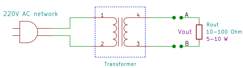 Figura 2: The connection diagram for the measurement of the transformer.
To perform the measurement, this material is required:
- The transformer to be measured;
- A multimeter allowing to measure alternated currents (almost all models allow this);
- A resistor with a value between 10 Ω and 100 &Omega, with high power (5 W or more, according to the transformer);
- A plug in order to connect the transformer to the power grid.
The measurement procedure is very simple:
- Measure the no-load voltage Vs(in this case it's equal to Vout);
- Connect the load resistor to the transformer output (please remember it must have low resistance values, between 10 Ω e i 100 &Omega, and a high power, 5 W or more);
- Measure the output voltage Vout at the resistor (that is, between A and B);
- Compute the transformer power as:
 where:
- Vs is the no-load voltage at the transformer output;
- Vout is the voltage at the resistor;
- Rout is the value of the resistor;
- n is an empirical value comprised between 0.8 and 0.9, typically 0.85.
It is possible to repeat the measure with many load resistors, in order to be able to plot the current-voltage plot to verify the precision of the measurement.
3 - The load resistor
The choice of the load resistor is important for the measurement. In theory, every value can be used. In practice, due to the limited multimeter resolution, it's better to choose a low resistance, for example 10 Ω or 100 Ω, in order to produce a high voltage drop at the transformer output. In this way the measure uncertainties are reduced.
Moreover, since it will have to dissipate a lot of heat, it's better to use a high power resistor, for example 5W or more, according to the transformer; the value can be computed as:
 where
where
- PRout is the power of the resistor;
- Vs is the no-load transformer output voltage;
- Rout is the test resistor;
In practical situations, resistors with lower powers can be used, provided that they are connected only for a few seconds; being indeed undersized, their overheating causes first a shift in their resistance value, and then their breaking. If adequate power resistors are missing, series or parallel resistors can be used, in order to distribute the total power. An example is shown in Figura 3.
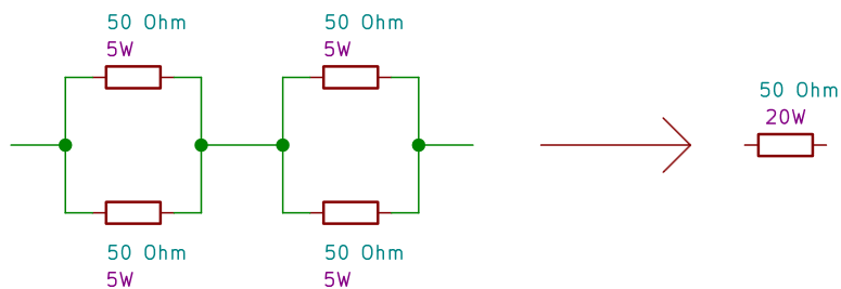 Figura 3: A possible configuration to combine resistors with the same values in series and parallel in order to obtain an equivalent circuit with the same resistance but higher dissipated power.
4 - The current - voltage plot
Once the voltage on the load Rout has been measured, it's possible to compute the supplied current with the Ohm law. If more measurements with various Rout values are performed, a voltage-current curve can be plotted, in order to verify the precision of the measurement. In case of a correct estimation, the plot is a line, which confirms the transformer ohmic behaviour when it is not supplying too much power. If the load resistor Rout is too small, that is if the power supplied by the transformer is very high, various physical phenomena would take place, such as the core saturation, which would make the transformer behaviour no longer linear; this would result in a voltage-current curve no longer straight. Moreover, in case there's an error in the measurement (wrong Rout or Vout values) the curve helps to find it.
5 - Example: transformer 1
The considered transformer has the following dimensions:
- Output type: alternated current
- Rated voltage: 12 V
- No-load measured voltage: 14,2 V
- Rated power:20 VA
The Tabella 1 shows various measurements performed on the transformer with various load resistors. Only one would be enough to compute the maximum power with the Formula 1, but in this way it's possible to plot the graph in Figura 5 to test that the transformer has basically an ohmic behaviour. From the values obtained in the table it's possible to determine that the best estimation is for n=0.9, that is when the output voltage is the 90% of the no-load one.
 Figura 4: The transformer 1 used in this example
| Load voltage Vout | Load resistor Rout | Load current Iout | Power for n=0.9 [W] | Power for n=0.8 [W] | Internar resistance RS |
|---|---|---|---|---|---|
| 14,2 | ∞ | 0 | |||
| 14 | 73,7 | 0,19 | 17,24 | 30,64 | 1,05 |
| 13,89 | 46,1 | 0,30 | 17,64 | 31,36 | 1,03 |
| 13,64 | 22,4 | 0,61 | 19,73 | 35,08 | 0,92 |
| 13,35 | 15 | 0,89 | 19,00 | 33,78 | 0,96 |
| 12,25 | 7 | 1,75 | 16,29 | 28,95 | 1,11 |
| Average: | 18 | 32 | 1,04 | ||
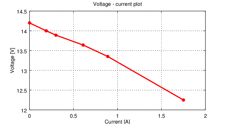 Figura 5: The transformer voltage-current plot, obtained through multiple measures with different load resistors. It's a straight line, and this confirms the linear behaviour, that is ohmic behaviour, of the transformer.
6 - Example: transformer 2
The second example transformer has the following properties:
- Output type: alternate current
- Rated voltage: 14 V
- No-load measured voltage: 15,58 V
- Rated power: 24 VA
As in case of the first example, the Tabella 2 resumes the measurement results, plotted in the graph of Figura 5. In this case the best estimation is for a factor n=0.8, that is where the output voltage is the 80% of the no-load one.
 Figura 6: The transformer 2 used in this example.
| Load voltage Vout | Load resistor Rout | Load current Iout | Power for n=0.9 [W] | Power for n=0.8 [W] | Internal resistance RS |
|---|---|---|---|---|---|
| 15,58 | ∞ | 0 | |||
| 15,33 | 73,7 | 0,21 | 18,18 | 32,31 | 1,20 |
| 15,15 | 46,1 | 0,33 | 16,70 | 29,68 | 1,31 |
| 14,68 | 22,4 | 0,66 | 15,91 | 28,28 | 1,37 |
| 14,16 | 15 | 0,94 | 14,52 | 25,82 | 1,50 |
| 12,4 | 7 | 1,77 | 12,17 | 21,63 | 1,80 |
| Average: | 15 | 27 | 1,43 | ||
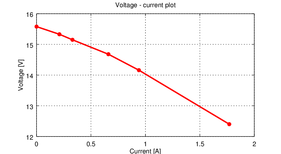 Figura 7: As in case of transformer 1, the voltage - current plot confirms the linear and ohmic behaviour of this device.
7 - The theory
In this section the origin of the formula used to compute the maximum transformer power is shown. There are many equivalent circuits for a transformer output port; among the most simple ones, the one that simplifies it to common generator with a series internal resistor, as shown in Figura 8.
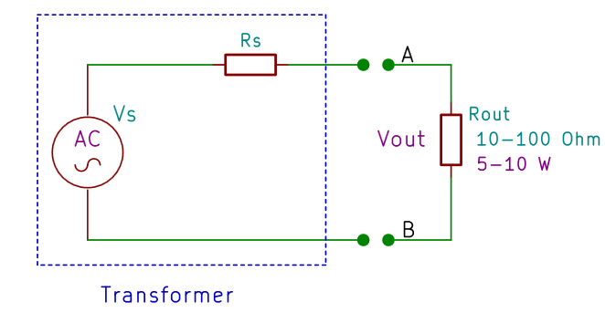 Figura 8: The transformer Thevenin equivalent circuit.
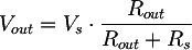 from which we can compute the internal resistance as:
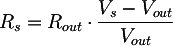
Please remember that the maximum power supplied by the transformer is when its output voltage is between 80% and 90% of its no-load voltage. Defining the parameter n, comprised between 0.8 and 0.9, the output voltage Vout n, corresponding to the maximum output power, is:
 We can therefore find the value of the resistor Routn that, connected to the transformer, allow us to obtain the voltage Voutn for the maximum power; that is, we are going to compute the load to be connected to the transformer to drain from it the maximum power. From the previously computed voltage divider we obtain:
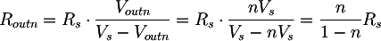 The power with Vout n and Rout n is therefore:
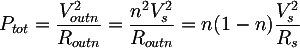 From which, substituting the expression of Rs found before, we can obtain the final formula:
Copyright 2014-2026 electroimc.com