


Subwoofer passive low pass filter
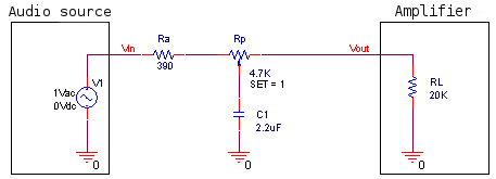 Figura 1
This article deals with the project of a simple first order passive low pass filter, which is designed to be placed before an audio amplifier connected to a subwoofer loudspeaker. The circuit, which uses audio line level signals, has an adjustable cutoff frequency between 20 Hz and 200 Hz. Since no active components are used, it is really simple to build, but the cutoff frequency depends on the output impedance of the audio source and on the input impedance of the amplifier. For the circuit presented here typical values will be assumed for these parameters, though it is a good idea to repeat the calculations for each amplifier. For a more precise but complex solution, a Subwoofer active low pass filter can be used.
1 - Circuit properties
In the following pictures the filter frequency response for f0 e f1, which are the minimum and the maximum cutoff frequencies, are shown. A graph with the frequency response variation as a function of the potentiometer is also presented.
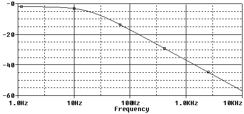 Figura 2: Filter transfer function module in dB, for fc = 20 Hz. On the abscissa the frequency is shown in a logarithmic scale.
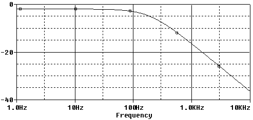 Figura 3: Filter transfer function module in dB, for fc = 200 Hz. On the abscissa the frequency is shown in a logarithmic scale.
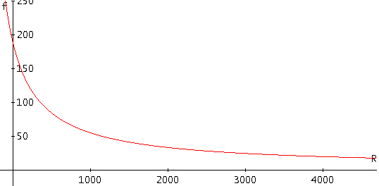 Figura 4: Filter cutoff frequency as a function of the potentiometer value.
1.1 - Signal loss
As usual, a passive filter introduces an attenuation A for the non filtered signal below fc, which is:
 This formula can be obtained substituting 0 into the s variable in the filter transfer function presented in section 2. In case of the filter shown in this article, A = 0.8. Said in other terms, the loss on the signal is about -1dB, which is acceptable.
2 - Circuit analysis and project
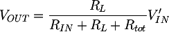
The circuit transfer function is:
 and its cutoff frequency:
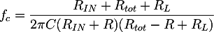 where Rtot is the RP potentiometer total resistance, and R is the partial value assumed by the potentiometer. To calculate the components values, an equation system can be written using the cutoff frequency formula evaluated in the two limit cases:
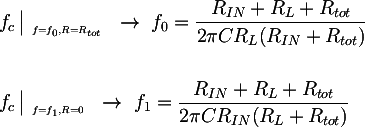 Where f0 = 20 Hz and f1 = 200 Hz. The solution of the system is the following:
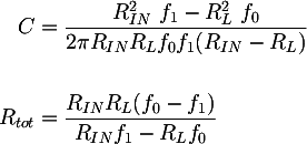
Some considerations can now be done to determine the numerical values to be inserted in the two expressions. The output impedance of the modern audio players or computers is very low, about some Ω, and therefore it can be neglected. The amplifier input impedance on the contrary is very important. RL=20KΩ is a common value, found for example in the Fenice 20, a hi-fi, T class, 15+15 W audio amplifier based on the Tripath TA2024C. Its value was measured with this method: Cheap measurement of an audio amplifier input impedance. Substituting the previous values in the equation system and choosing for example RA = 390 Ω the other components values can be calculated: C = 2.2uF and RP = 4.7 KΩ.
Bibliography and other documents
Copyright 2014-2024 electroimc.com